

Top Uniaxial Geogrid Applications for Stronger Soil Reinforcement and Long-Term Stability
2026-11-16
Soil failure rarely gives a warning—until a retaining wall starts leaning or a paved surface cracks under pressure. Uniaxial geogrids change that equation by concentrating tensile strength where soil needs it most, making them a practical choice for projects that cannot afford slow deformation. From reinforced slopes and segmental retaining walls to heavy-duty embankments and access roads, these grids lock fill material into a more stable, load-sharing structure. Sourcing from WEN FENG STONE adds another layer of confidence, especially when specifications demand consistent aperture geometry and long-term creep resistance. This article walks through the applications that deliver the clearest gains in soil reinforcement, along with the design factors that separate dependable performance from early failure.
Where Uniaxial Geogrids Earn Their Keep in Retaining Structures
Uniaxial geogrids prove most valuable in retaining walls where the dominant load pulls in a single direction, typically outward from the face. Their longitudinal ribs carry the tensile forces while the transverse bars anchor into compacted backfill, letting the structure hold grades that would otherwise demand far more concrete or a gentler slope.
This advantage becomes especially clear on soft subgrades and in tight work areas. Because the grid distributes stress over a broad plane, it reduces differential settlement and allows crews to build taller, near-vertical faces without the curing time or heavy equipment that cast-in-place walls usually require. In those conditions, the geogrid is not simply an add-on; it often makes the wall feasible at all.
Steep Slopes That Hold Up Without Bulging
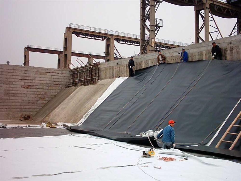
Steep slopes rarely fail because the soil itself is weak; they fail because water and poor compaction push the face outward. A slope that holds shape without bulging usually has a slight backward lean into the hill, not a perfectly vertical cut. That batter shifts the center of mass behind the face and gives the lower section more room to carry the load. Compaction lifts are kept thin, and each layer is moistened just enough to bind without trapping water.
Behind the face, drainage does more than a thick wall ever could. A narrow strip of clean crushed stone with a perforated pipe at the base stops hydrostatic pressure before it can bow the slope. Even dense clay can be used, provided the surface is graded to shed water quickly and planted with deep-rooted ground cover that locks the upper few feet. The visible face may be stone, timber, or modular block, but the real stability is in the wedge of compacted earth directly behind it.
Reinforced Foundations for Heavily Loaded Ground
Heavy loads don't just press down on a slab—they push sideways into the soil, force moisture to migrate, and create differential settlement that shows up as cracks long before anyone notices a problem. A reinforced foundation starts with understanding which failure mode is most likely: edge shear under crane rails, center flexure beneath storage racks, or rotational movement around a machine base that vibrates constantly. Instead of relying on generic mats of rebar, the design shifts to deeper, targeted reinforcement—hairpins at corners, buried beams under concentrated posts, and sometimes a thickened edge that changes the slab from a passive plate into a load-distributing system.
The subgrade matters more than most people admit. You can pour twice the concrete and still see failures if the soil beneath isn't prepared to share the load path. For heavily loaded ground, that often means compacting in lifts with a specific moisture window, then adding a geogrid or aggregate layer that prevents fines from pumping upward under repeated cycles. Some sites benefit from a lean concrete subbase—not because the top slab needs it structurally, but because it gives the reinforcement a stable bed and keeps the rebar from sagging into soft spots before the pour.
Reinforcement details tend to follow what the future loads will actually do, not what a standard table says. If a forklift runs the same aisle a thousand times a day, the steel layout near the joint spacing gets tighter and the dowels shift to plate dowels with welded clips. If a tank farm sits in one area with periodic surge loads, the foundation may step down in thickness and transition with a grade beam that absorbs the stiffness change. The goal isn't just to add more steel—it's to put the right kind of restraint exactly where the ground tries to move, so the concrete stays whole under loads that would overwhelm a conventional slab.
Paved Roads That Resist Rutting and Reflective Cracks
Rutting and reflective cracking are two of the most persistent forms of distress in asphalt pavements, especially in regions with heavy truck traffic or extreme temperature swings. Rutting typically shows up as longitudinal depressions in the wheel paths, caused by a combination of insufficient mix stability, high pavement temperatures, and repeated loading. Reflective cracks, on the other hand, occur when existing cracks or joints in an underlying layer propagate upward through a new overlay. Addressing both issues at once requires a deliberate shift in mix design and structural strategy, rather than relying solely on thicker lifts or routine resurfacing.
One practical approach is to use polymer-modified binders with a higher high-temperature performance grade, which improves resistance to permanent deformation without sacrificing low-temperature flexibility. Pairing this with a stone-on-stone aggregate skeleton, such as a well-graded stone matrix asphalt or a dense-graded mix with strong internal friction, gives the pavement enough interlock to shed load before it can shear the binder. For reflective cracking, placing a stress-absorbing membrane interlayer or a geosynthetic reinforcement beneath the new surface can interrupt crack propagation. These interlayers act as a buffer, distributing strain over a wider area instead of letting it concentrate at the tip of an old crack.
Field performance also depends heavily on construction details that are easy to overlook. Compaction density should stay above 92 to 93 percent of theoretical maximum, because under-compacted mats are more prone to both rutting and early crack reflection. Joint construction, tack coat uniformity, and milled surface cleanliness matter just as much as the mix recipe. Where budgets allow, a thin bonded overlay or a high-modulus asphalt concrete layer can add another line of defense. Ultimately, the goal is not to chase a single magic additive but to combine a rut-resistant mix, a crack-mitigating interlayer, and tight paving practices into one coherent system.
Landfill Base Layers Built for Uneven Settlement
Differential settlement under a landfill rarely shows up as a sudden, visible drop. It develops over years as waste decomposes, soft subgrades consolidate, or pockets of weaker ground give way at different rates. Base layers have to absorb that slow deformation without tearing the liner system above them. This often means placing a cushion of select soil or geotextile over the prepared subgrade, then building the barrier upward with enough flexibility to bridge small depressions as they form.
A base layer designed for uneven settlement tends to sacrifice stiffness for ductility. Instead of relying on a rigid platform, engineers use compacted clay, reinforced soil, or geosynthetic reinforcement that can elongate slightly under local strain. Field crews pay close attention to lift thickness and moisture control during compaction, since a dense but brittle base can crack just when the ground beneath it moves. The goal is to keep the overlying geomembrane and drainage layer working as a continuous barrier, even if the settlement profile becomes irregular.
Some sites go further by grading the subgrade to direct water away from expected low spots and by sequencing fill placement to let soft areas consolidate before the liner is installed. Monitoring points may be placed under the base layer to track early movement, giving operators time to adjust grades or add fill before small depressions turn into liner-straining basins. Those small adjustments, repeated across the footprint, are often what keep a landfill base intact when the ground refuses to settle uniformly.
Working Platforms That Keep Heavy Equipment Moving
On heavy industrial sites, downtime isn't measured in minutes—it gets counted in lost loads and stalled schedules. That's where a properly built working platform earns its keep. These aren't simple scaffolds; they are load-rated access decks, service bays, and mobile lifts sized for machines that weigh more than a loaded truck. A platform that keeps equipment moving has to handle constant vibration, uneven tire loads, and the occasional dropped tool without flexing or shifting.
The best setups combine grip, clearance, and easy repositioning. Look for bolt-together steel or aluminum decks with slip-resistant tread plate, raised edges, and ramps that line up with trailer heights. Locking casters or hydraulic leveling legs allow a crew to roll the platform into place, set it, and get to work on undercarriages, tracks, or final drives. When the platform moves with the job, the machine returns to service faster.
In mining, rail, and large-fleet shops, modular designs make the difference. Panels can be added or removed as equipment footprints change, and load ratings often start around several tons and climb from there. Instead of waiting on a crane or custom fabrication, maintenance teams reconfigure the same deck sections for wheel loaders one week and articulated haulers the next. That flexibility keeps heavy equipment moving without putting technicians at risk.
FAQ
Most of the difference comes down to the aperture shape and the way stress is handled. In a uniaxial geogrid, the ribs are drawn mainly in one direction, so the junctions and apertures are built to transfer load into the surrounding compacted soil rather than just acting as a flat tensile sheet. That interlock mechanism reduces the chance of pullout and keeps creep deformation low under sustained loads, which is what you need for walls and slopes that are expected to perform for decades.
Mechanically stabilized earth walls and bridge abutments usually show the clearest benefits. Because the grid resists the horizontal earth pressure so efficiently, you can build taller walls without pouring massive concrete sections or using deep foundations. The facing can be precast panels, modular blocks, or even a wrapped face, and the reinforced soil mass acts more like a coherent block than a loose wedge.
When the ground below is soft, the main risk is that the embankment load will squeeze the foundation and cause localized shear failure. A uniaxial geogrid placed at the base helps spread that load over a wider area and adds enough tensile restraint to keep the fill from spreading sideways. That reduces differential settlement and buys time for pore pressures to dissipate, so the project can proceed instead of waiting for full consolidation.
They allow you to steepen the slope face because each reinforcement layer holds back a portion of the soil mass. In many cases you can switch from a long, shallow vegetated slope to a much shorter, near-vertical reinforced slope that occupies less land. With a wrapped face and topsoil, grass or native planting can still be established, so the finished surface blends better with the surrounding landscape than a concrete wall would.
Poor tensioning and sloppy fill placement are probably the biggest ones. If the grid is not pulled tight before backfill is placed, it cannot engage until the soil has already moved too much. Insufficient overlap between adjacent rolls, using fill with large angular rocks directly against the grid, or compacting with the wrong equipment can also tear ribs or damage junctions. Drainage gets overlooked sometimes too, and trapped water behind a reinforced soil mass creates extra hydrostatic pressure that shortens the service life.
Yes, and often the best results come from a combination approach. For example, a geogrid can be used with vertical drains or stone columns to handle both reinforcement and drainage in soft ground. In slope work, soil nails or rock bolts can handle deeper instability while the geogrid reinforces the near-surface fill. Just make sure the construction sequence is planned so each component engages the way the designer intended, otherwise one layer can end up doing nothing until the other has already deformed.
Long-term design strength should be checked against the expected soil temperature, chemical environment, and installation damage level. Junction efficiency matters because a grid with weak connections between ribs will not transfer load into the soil effectively. Look at creep behavior under the project's sustained load duration, and ask for data that shows the product can survive the specified backfill and compaction method. Cheaper upfront material is not much of a saving if you have to add more layers or accept a shorter design life.
Conclusion
Uniaxial geogrids earn their keep when soil has to hold a shape or carry a load that compacted fill alone cannot handle. In retaining walls and steep slope reinforcement, the grid locks into compacted layers and carries tensile stress well back from the face, which keeps walls plumb and slope lines sharp instead of letting the toe bulge outward. That same idea shows up in reinforced foundations and working platforms, where heavy wheel or structural loads press down on soft ground. The geogrid confines the aggregate and restricts lateral movement, so crane pads, haul roads, and heavily loaded footings stay stable without deep excavation or an overbuilt stone section.
Paved roads are a less obvious but equally practical case. A uniaxial geogrid placed within or under the base course shields the asphalt from differential movement that eventually shows up as rutting and reflective cracks, and that protection stretches the pavement's useful life under steady traffic. Landfill base layers pose another problem because waste settles unevenly over time. In that setting, the geogrid behaves like a load-transferring membrane, bridging soft zones and lowering the risk of liner stress or localized failure. Across these situations, the long-term payoff is similar: the geogrid stabilizes soil from within, so settlement, lateral spread, and surface damage are managed before they demand costly repairs.
Contact Us
Contact Person: Jennifer LEE
Email: [email protected]
Tel/WhatsApp: 8618553418999
Website: https://vip.e-baixing.com/wenfengshitong