
Vertical Lift Plating Equipment for OEM Motorcycle Parts A Complete Guide
2026-09-09
When it comes to plating OEM motorcycle parts, the difference between a flawless finish and a costly rework often comes down to one thing: the lift system. Vertical lift plating equipment has quietly become the backbone of high-volume production lines, but choosing and optimizing the right setup is far from straightforward. In this complete guide, we’ll break down the key design considerations, plating uniformity, and maintenance strategies—so you can stop troubleshooting guesswork and start producing parts that meet OEM specs consistently. Whether you're upgrading an existing line or building a new one, the insights here will help you avoid the pitfalls that stall most projects. And if you're looking for a partner who understands these systems inside out, Junda brings years of hands-on expertise to the table. Let’s dive in.
Why Vertical Lift Systems Outperform Barrel Plating for Complex Motorcycle Components
Motorcycle parts like brake calipers, triple clamps, and intricate engine covers rarely play nice with the tumbling action of barrel plating. Every rotation bangs components against each other, and that's a quick way to introduce dings, scratches, or uneven coverage on threads and recessed areas. Vertical lift systems take a completely different route: parts are mounted on racks and immersed in the plating bath without colliding. The result is a finish that holds up under close inspection, with sharp edges and delicate geometries preserved exactly as they were machined.
Another point that often goes unnoticed is how current distribution shifts when parts are free to move. In a barrel, contact between components is constantly changing, which means plating thickness can vary from piece to piece or even across a single part. Vertical lift systems keep each part at a fixed distance from the anodes, allowing for more predictable metal deposition. For complex motorcycle components where tolerances matter and post-plating assembly fits are tight, this consistency saves a lot of rework and scrapped parts.
Finally, there's the practical side of handling and process control. Racking parts individually in a vertical lift system makes it easier to mask off specific areas, inspect pieces before and after plating, and avoid the frustrating hunt for small components lost at the bottom of a barrel. Shops that deal with low-volume, high-value motorcycle hardware quickly realize that the gentler handling and repeatable results more than justify the switch away from barrel methods.
How Adjustable Lift Cycles Prevent Uneven Deposition on Cast Aluminum Housings
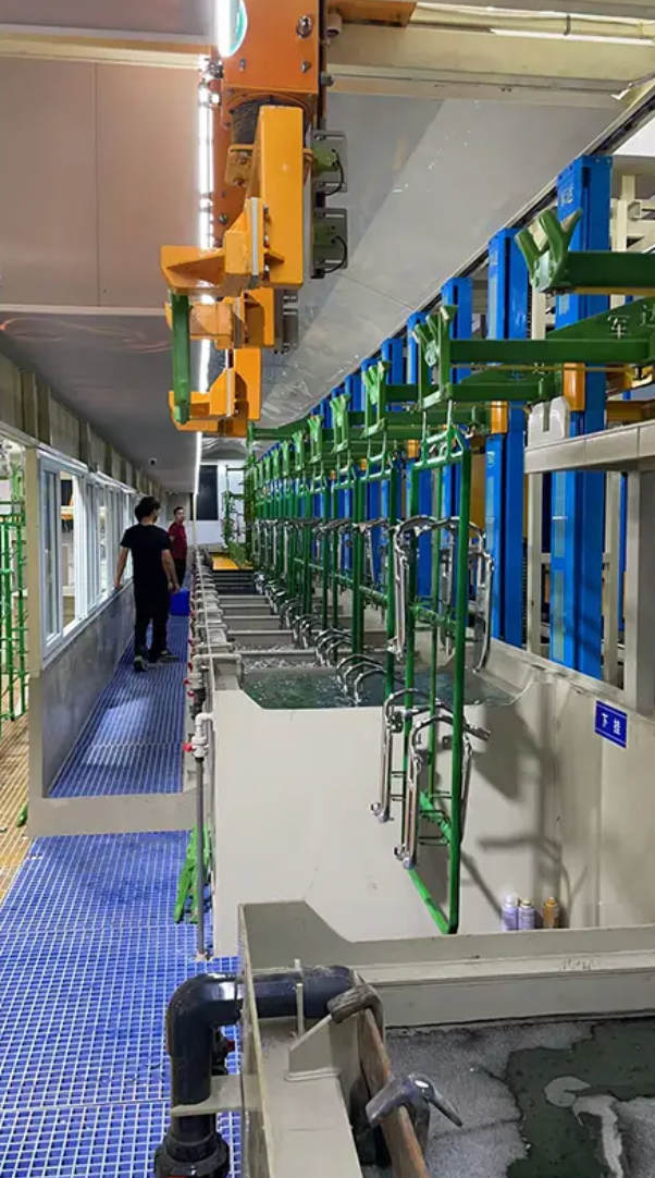
The uneven buildup on cast aluminum housings rarely comes from a single cause. It usually starts with the part's own geometry—deep pockets, sharp corners, and thin walls all pull current differently in the bath. Adjustable lift cycles let the line operator change how the rack moves through the solution instead of relying solely on bath chemistry or anode placement. By altering stroke length, speed, and dwell time at the ends of the stroke, the movement breaks up stagnant pockets and refreshes the solution around recessed areas that a fixed immersion depth would leave starved.
This becomes especially useful on cast surfaces, where porosity and small inclusions can disrupt local flow. A standard lift profile may work for flat panels but will often leave thin or rough deposits inside fins or mounting bosses. With an adjustable cycle, the housing can be moved more slowly through high-current zones and paused briefly at the top of the stroke to release hydrogen or trapped air. Those pauses reduce pitting and burning that are common when gas bubbles cling to the aluminum surface. Once a profile is tuned for a particular housing design, it can be stored and reused, eliminating repeated manual adjustments.
In practice, operators compare coating thickness at several points after a trial run. If the lower cavity reads below spec, they extend the bottom dwell or increase the travel distance. If edges are building up too fast, they slow the acceleration or add a longer rest at the top. Because these changes are made in the control program rather than to the tank hardware, the same line can switch between different housing geometries with little downtime. The result is a more uniform deposit and fewer rejects from uneven coverage.
Matching Chemical Baths to Motorcycle Alloys Without Cross-Contamination
Aluminum, magnesium, and titanium each demand a different chemical personality from the bath. A caustic soda solution that strips oxidation from an aluminum fork leg will pit a magnesium engine cover within minutes. Dropping a titanium fastener into the same acidic pickling tank used for steel only breeds hydrogen embrittlement and a dull, uneven finish. The practical rule is simple: one alloy, one dedicated bath, no exceptions when you care about fatigue life.
Cross-contamination rarely announces itself. It shows up later as white bloom on a freshly anodized swingarm or a dull patch on a polished magnesium wheel where copper ions from a previous steel run have deposited. To prevent this, use separate tanks, color-coded lids, and alloy-specific filtration media. Rinse water between steps matters just as much—drag-out from a chrome passivation bath will poison an aluminum conversion coating if the intermediate rinse is skipped or shared.
Small shops can manage the risk with a staged workflow. Run all steel parts on one day, drain and scrub the tanks, then run aluminum the next. Keep a log of bath pH, temperature, and last alloy processed. Replace the rinse water after each family of metals, and never let a part sit in a bath longer than the spec sheet allows. The goal is not a pristine lab, but a predictable sequence so that the next set of engine cases comes out clean, sound, and free of someone else's chemistry.
Reducing Floor Space and Energy Draw in Mid-Volume OEM Plating Lines
Mid-volume OEM plating operations often inherit layouts from higher-throughput lines, leaving unused floor space and oversized support equipment. Tightening the footprint starts with rethinking tank spacing and auxiliary systems. Narrower, deeper process tanks with shared overflow weirs and common service corridors cut square footage without sacrificing part access. Pairing this with overhead hoist paths that run closer to tank rims reduces crane clearance zones and lets operators place more process steps in the same building bay.
Energy draw in these lines typically comes from three places: rectifiers, bath heating, and exhaust. Replacing older silicon-controlled rectifiers with high-frequency switch-mode units improves conversion efficiency at partial loads, which is where mid-volume lines spend most of their time. Bath heating can be trimmed by adding insulated tank covers and heat exchangers that recover waste heat from rinse water or from the rectifier cooling loop. On the exhaust side, variable-speed fans tied to tank covers or load sensors drop airflow when stations are idle, cutting both fan power and conditioned makeup air demand.
A further step is to consolidate plating steps that share chemistry. For example, running a single nickel bath with pulse-reverse capability instead of separate semi-bright and bright nickel tanks reduces both floor area and total heating load. In mid-volume OEM work, this kind of line balancing often delivers more savings than chasing marginal reductions in individual component efficiency.
Maintaining Consistent Thickness on Threaded Fasteners and Small Brackets
Keeping plate thickness uniform across threaded fasteners and small brackets starts with racking. Parts that touch or shield each other will inevitably build more deposit in some areas and less in others, so orient threads downward and space brackets far enough apart that solution flows freely through every recess. A quick check under magnification after the first few runs usually reveals whether contact points are stealing current.
Threads are especially prone to excess buildup because their peaks attract more current than the roots. To counter this, reduce the average current density and use a bath with better throwing power, or apply a conforming anode that follows the part profile. For small brackets, watch the inside corners, where plating tends to thin out just where stress concentrates. A slight reduction in rack density often does more than adjusting chemistry.
Verify thickness with a micrometer on flat reference surfaces, not on thread flanks where readings fluctuate. For batch consistency, pull samples from the same rack positions each time and record the variance. If the spread exceeds a few microns, look first at anode placement and agitation before changing the plating time, since those two factors drive most uneven growth on small hardware.
Questions to Ask Before Retrofitting an Existing Line for Vertical Lift Handling
Before you commit to a vertical lift retrofit, walk the actual floor and measure clearances that aren't obvious on drawings—overhead beams, sprinkler lines, and existing conveyor supports. Ask whether the lift can be installed without removing a load-bearing column or re-routing utilities. If the answer pushes you into major structural changes, the project may already be losing its payback.
Next, dig into the load itself. Pallet weights and sizes are just the start; ask what happens when a new product line introduces taller stacks or softer packaging. A lift that handles today's volume may stall if the upstream line feeds it in bursts rather than a steady stream. Get real cycle time data from the floor, not from the lift supplier's best-case spec sheet.
Before signing off, check how the lift will talk to your existing controls. Will a new PLC rack be needed, or can it piggyback on the current network? Ask who handles the safety validation and whether local technicians can get parts without waiting weeks. These questions rarely show up in a quote, but they determine whether the retrofit runs quietly or becomes a daily headache.
FAQ
Vertical lift plating equipment uses an elevator-style transport system to move parts vertically through a series of process tanks. Unlike conventional hoist or barrel lines, the vertical motion reduces footprint, improves drainage between stages, and gives more consistent immersion angles - especially useful for complex OEM motorcycle components like wheels, fork tubes, and brake calipers.
OEM motorcycle parts often have tight dimensional tolerances and visible surface finish requirements. Vertical lift systems allow precise control of immersion depth and dwell time, which helps achieve uniform coating thickness on intricate shapes. The design also minimizes part-to-part contact, reducing the risk of nicks or shadowing that can occur in barrel plating.
The vertical arrangement packs more process stages into a smaller floor area, which lowers factory overhead. It also shortens transfer time between tanks, cutting cycle times. Plus, the automated lift sequence can be finely tuned per part recipe, so a single line can handle multiple OEM part numbers without mechanical changeovers.
Because parts are lifted straight up out of a solution, fluid sheets off more evenly than when tilted or swung. That means less drag-out of plating solution into rinse tanks, which reduces chemical waste and improves rinse effectiveness. Many lines also integrate drip trays or blow-off stations right above the tank to capture and return excess solution.
You will see it used for steel or aluminum parts that need corrosion protection plus a decorative or functional finish - things like handlebar mounts, foot peg brackets, axles, sprocket carriers, engine covers, and various fasteners. It is also common for zinc-nickel or electroless nickel plating on safety-critical components.
Key considerations include the lift's positional repeatability, the ability to store multiple part recipes, tank layout flexibility, ventilation and containment, and how easily the line can be expanded or reconfigured. Also evaluate the PLC/HMI interface - operators should be able to adjust lift speed, dwell, and agitation without programming skills.
The vertical lift rails and bearings need regular lubrication and alignment checks, as any wobble can cause uneven plating or drips between tanks. Chemical fumes can corrode lift components if the line is not properly ventilated. Also, if the lift fails mid-cycle, parts may be stuck in a bath, so backup controls or manual override are essential.
Operators do not need to lean over open tanks or manually transfer racks because the automated lift handles all vertical movement. Enclosed tunnel designs with exhaust capture reduce exposure to mists and fumes. Emergency stop systems and interlocked doors prevent access while the lift is in motion.
Conclusion
Relying on barrel plating for intricate OEM motorcycle components often leaves corners starved and recesses overbuilt. Vertical lift systems change that dynamic by positioning parts so solution flows across every surface, including cast aluminum housings where blind pockets and varying wall thickness demand precise control. Adjustable lift cycles let operators tune immersion and withdrawal speeds to match geometry, preventing edge buildup and thin spots that plague fasteners and small brackets. Because each rack can be dedicated to a single alloy family, the risk of cross-contamination between magnesium, zinc, and aluminum baths drops sharply, preserving bath chemistry and finish quality without constant dumping and recharging.
For mid-volume production, vertical lift lines shrink the footprint compared to long barrel or overhead monorail setups, and the pumps and heaters run closer to actual demand, cutting energy draw during slow shifts. Threaded fasteners and small brackets benefit from consistent thickness because lift agitation keeps current density more uniform than tumbling, where parts can nest or shield one another. Before retrofitting an existing line for vertical lift handling, verify whether your current rectifier and tank layout can support the new rack spacing, whether your overhead structure can handle the additional lift weight, and whether your wastewater treatment can cope with the different drag-out patterns. Answering these questions early prevents costly downtime and ensures the new system delivers its promised gains in adhesion, corrosion resistance, and production flexibility.
Contact Us
Contact Person: hayyr
Email: [email protected]
Tel/WhatsApp: 8613082110525
Website: https://www.jundaelectroplating.com